Kohler K-1394-H2-96 Installation Guide Page 8
- Page / 56
- Table of contents
- BOOKMARKS
- Installation Guide 1
- Important Information 2
- Table of Contents 3
- Before You Begin 3
- Tools and Materials 4
- 1. Prepare the Site 5
- 2. Prepare the Whirlpool 5
- Apply construction 6
- 5. Install the Plumbing 7
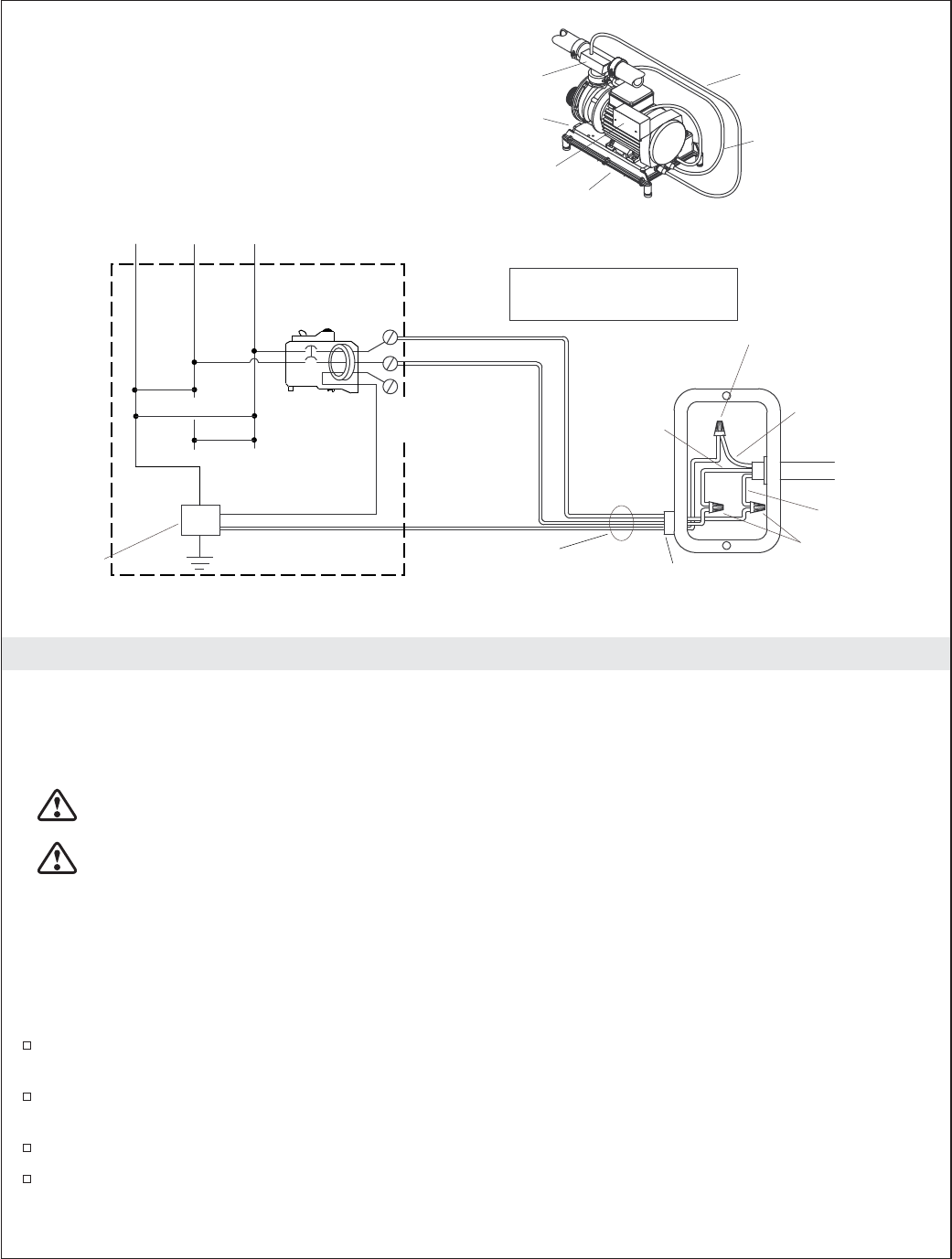
- Electrician to provide 8
- Kohler Co. 9 1022205-2-D 9
- 8. Test Run the Whirlpool 10
- Drop-In Installation 11
- Flush Installation 11
- Whirlpool 11
- Three pillows are shown 12
- 12. Confirm Proper Operation 13
- 13. Operating Sequence 14
- 15. Remote Control Operation 15
- Troubleshooting 15
- 14. Chromatherapy Operation 15
- Guide d’installation 19
- Sommaire 20
- Avant de commencer 20
- Outils et matériaux 21
- 1. Préparer le site 22
- 5. Installer la plomberie 24
- L'électricien doit 25
- Logement 27
- - quatre coussins sont inclus 30
- Couvercle d'aspiration 31
- Riverjet 31
- Dépannage 33
- Guía de instalación 37
- Contenido 38
- Antes de comenzar 38
- Herramientas y materiales 39
- 1. Prepare el sitio 40
- Aplique adhesivo de 41
- 5. Instale la plomería 42
- Alojamiento 45
- Se ilustran tres almohadas 48
- Tapa de succión 49
- Jet Riverjet 49
- Guía para resolver problemas 51
- 1022205-2-D 55
Related products and manuals for Above ground pool accessories Kohler K-1394-H2-96


 (52 pages)
© 2020, manymanuals.com. All rights reserved. | 0.121 s |
 Manymanuals.com
 Manymanuals.de
 Manymanuals.fr
 Manymanuals.it
 Manymanuals.pl
 Manymanuals.cz
 Manymanuals.es
 Manymanuals-pt.com
Comments to this Manuals