Kohler Aegis LH640 User Manual Page 13
- Page / 20
- Table of contents
- TROUBLESHOOTING
- BOOKMARKS
- OWNER'S MANUAL 1
- Safety Precautions 2
- California 2
- Proposition 65 Warning 2
- Safety Precautions (Cont.) 3
- Oil Recommendations 4
- Fuel Recommendations 5
- Engine Identification Numbers 5
- Operating Instructions 6
- Starting 7
- Operating 7
- Maintenance Instructions 8
- Check Oil Level 9
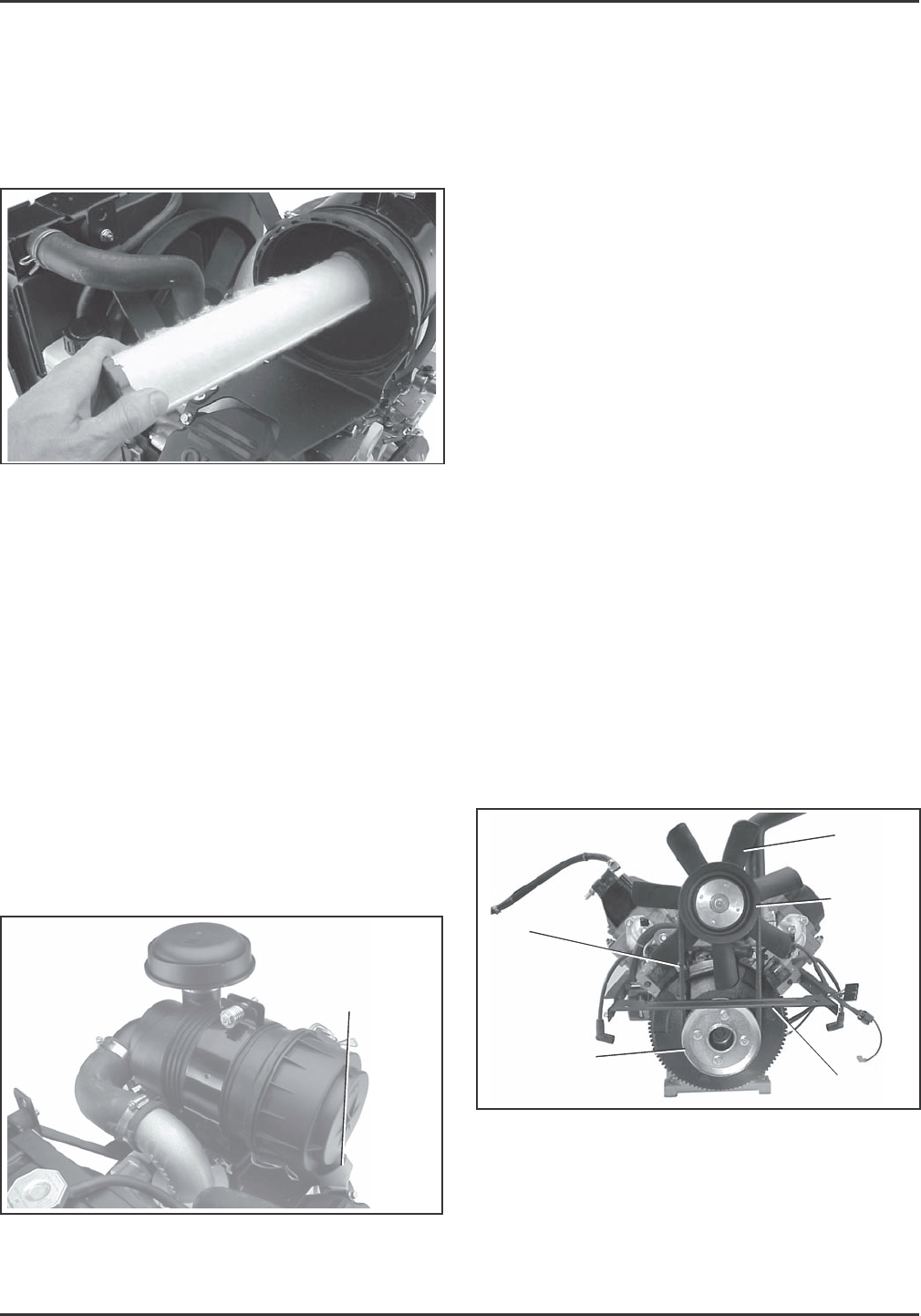
- Components 13
- Check Spark Plugs 14
- Battery Charging 15
- Adjustments 16
- Troubleshooting 17
- Specifications 18
- Parts Ordering 18
- Major Repair 18
- KohlerEngines.com 20
Related products and manuals for For the car Kohler Aegis LH640


 (120 pages)
(19 pages)
(20 pages)
(152 pages)
(16 pages)
(17 pages)
(20 pages)
(217 pages)
(24 pages)
(120 pages)
(19 pages)
(20 pages)
(152 pages)
(16 pages)
(17 pages)
(20 pages)
(217 pages)
(24 pages)
© 2020, manymanuals.com. All rights reserved. | 0.601 s |
 Manymanuals.com
 Manymanuals.de
 Manymanuals.fr
 Manymanuals.it
 Manymanuals.pl
 Manymanuals.cz
 Manymanuals.es
 Manymanuals-pt.com
Comments to this Manuals