Kohler 13ERG User Manual Page 27
- Page / 52
- Table of contents
- BOOKMARKS
- Installation 1
- Table of Contents 3
- Accidental Starting 5
- Engine Backfire/Flash 6
- Exhaust System 6
- Fuel System 7
- Hazardous Noise 7
- Hazardous Voltage/ 7
- Electrical Shock 7
- Hot Parts 8
- Moving Parts 8
- TP-6335 9/04 10
- Section 1 Introduction 11
- Introduction TP-6335 9/04 12
- 2.1 General Considerations 13
- 2.2 Location 13
- 2.3 Vehicle-Floor Mounting 13
- Section 3 Cooling System 15
- 6 Cooling System TP-6335 9/04 16
- Section 4 Exhaust System 17
- 4.1 Planning 18
- 4.2 Clearance Requirements 18
- 4.3 Exhaust Piping, If Used 18
- Section 5 Fuel System 19
- 5.2 Fuel Filters or Strainers 20
- 5.3 LP Gas 20
- 5.4 Fuel Pump Lift and Fuel 21
- Consumption 21
- TP-6335 9/0412 Fuel System 22
- Section 6 Electrical System 23
- 120 Volt 24
- 240 Volt 24
- 6.3 Circuit Protection 25
- Generator-End View 26
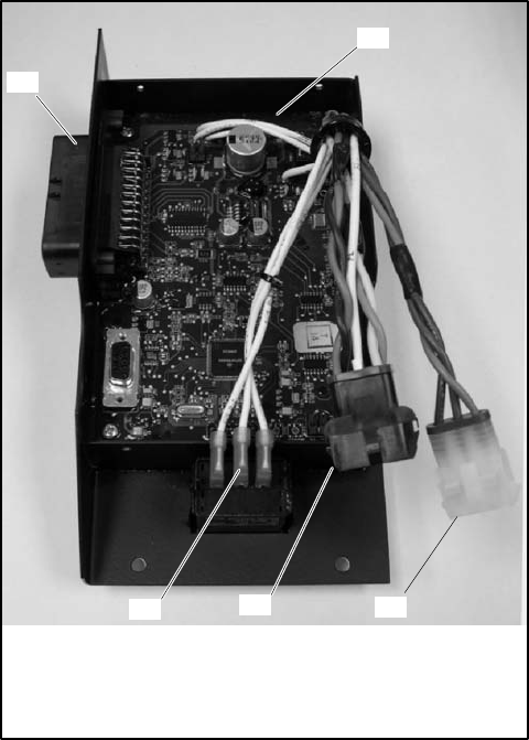
- 6.4 ADC 2100 Continuous Power 27
- Mode Jumper 27
- 6.5 Battery and Connections 28
- 6.6 Remote Connection 29
- ADV-6816A-A 31
- ADV-6816C-A 33
- 8.1 Four-Lead Reconnection 36
- 8.2 Advanced Digital Control 38
- (ADC 2100) 38
- Volts/Hz 39
- 8.2.4 Voltage Adjustment 39
- Continued on Figure 8-7 40
- Continued from Figure 8-6: 41
- General Wattage Requirements 47
- Appendix B Abbreviations 48
Related products and manuals for Generators Kohler 13ERG
 (72 pages)
© 2020, manymanuals.com. All rights reserved. | 1.843 s |
 Manymanuals.com
 Manymanuals.de
 Manymanuals.fr
 Manymanuals.it
 Manymanuals.pl
 Manymanuals.cz
 Manymanuals.es
 Manymanuals-pt.com
Comments to this Manuals