Kohler Power Systems 14/20RESA User Manual Page 29
- Page / 72
- Table of contents
- TROUBLESHOOTING
- BOOKMARKS
- 14/20RESA 1
- 14/20RESAL 1
- Operation 1
- Controller Identification 2
- Engine Identification 2
- Table of Contents 3
- Table of Contents, continued 4
- TP-6804 12/116 6
- Accidental Starting 7
- Engine Backfire/Flash 8
- Exhaust System 8
- Fuel System 9
- Hazardous Noise 9
- Hazardous Voltage/ 9
- Moving Parts 9
- Heavy Equipment 10
- Hot Parts 10
- Introduction 11
- Nameplate 12
- Emission Information 12
- Service Assistance 13
- RDC2 Controller Features 16
- DC2 Controller Features 17
- 1.7 Accessories 18
- 1.8 Service Views 19
- 2.1 Prestart Checklist 21
- 2.3 Generator Set Operation 21
- RXT Transfer Switch 22
- RDT or RSB Transfer Switches 22
- 2.4 Exercise 23
- 2.5 Faults 24
- Fault Shutdown 25
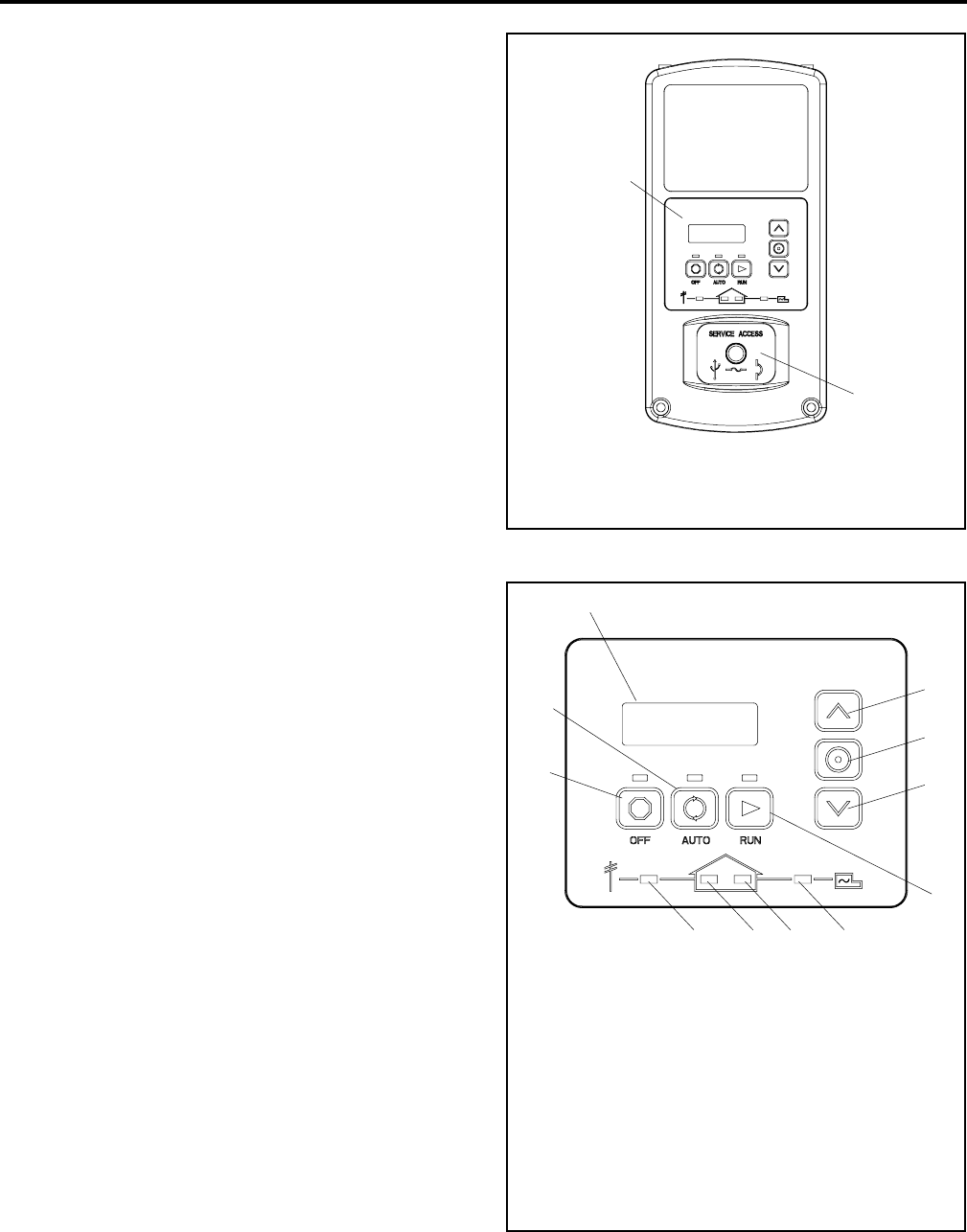
- Switch Controller 29
- 3.2 Controls and Indicators 29
- 3.2.1 Controller Keypad 30
- 3.2.2 LED Indicators 30
- 3.2.3 LCD Display 31
- 3.3 Controller Power 32
- 3.4 Battery Charging 32
- 3.5 Changing Settings 32
- 3.6 Setting the Exerciser 34
- 3.7 RDC2 Controller Menus 36
- 3.8 Main Menu 36
- 3.9 Overview Menu 37
- 3.10 Engine Metering Menu 37
- 3.11 Generator Metering Menu 38
- 3.13 Genset Run Time Menu 39
- 3.14 Genset System Menu 40
- 3.15 ATS Status Menu 41
- 3.16 ATS Configuration Menu 42
- 3.17 Date and Time Menu 43
- Submenu (OnCue Password) 45
- 3.18.3 RBUS Information 46
- 3.18.4 Remote Devices Submenu 47
- 3.19 Programmable Interface 48
- Module (PIM) Status Menu 48
- 3.21 Event Log 50
- 4.2 Controls and Indicators 51
- 4.2.1 Controller Keypad 52
- 4.2.2 LED Indicators 52
- 4.3 Controller Power 53
- 4.4 Battery Charging 53
- 4.5 Exercise 54
- 4.6 Event Log 54
- 4.7 Maintenance Timer 55
- 4.8 OnCue Password 55
- 5.1 Scheduled Maintenance 57
- 5.2 Lubrication System 60
- 5.2.6 Oil Cooler 20RESA/RESAL 61
- 5.3 Spark P lugs 62
- 5.4 Air Cleaner Service 62
- 1. Knobs (qty.2) 63
- 2. Cover 63
- 3. Paper element 63
- 5.5 Cooling System 64
- 5.6 Exhaust System 64
- 5.7 Battery 65
- 5.8 Storage Procedure 66
- Section 6 Troubleshooting 67
- 6.5 Troubleshooting 68
- Appendix A Abbreviations 69
- TP-6804 12/11 72
© 2020, manymanuals.com. All rights reserved. | 1.188 s |
 Manymanuals.com
 Manymanuals.de
 Manymanuals.fr
 Manymanuals.it
 Manymanuals.pl
 Manymanuals.cz
 Manymanuals.es
 Manymanuals-pt.com
Comments to this Manuals