Kohler K-1166-C1-96 Installation Guide Page 11
- Page / 64
- Table of contents
- BOOKMARKS
- Installation Guide 1
- Important Information 2
- Tools and Materials 3
- Before You Begin 3
- List of New Terms 5
- 1. Roughing-In Information 6
- 2. Construct the Stud Framing 7
- 3. Install the Rough Plumbing 8
- 4. Prepare the Unit 8
- 5. Position the Unit 9
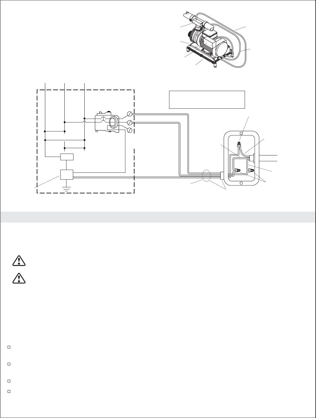
- 7. Install the Plumbing 10
- 1054216-2-B 12 Kohler Co 12
- 11. Using the Remote Control 14
- 13. Install the Faucet Trim 15
- 15. Using Your Bath 16
- Guide d’installation 19
- Renseignements importants 19
- Outils et matériels 20
- Introduction 20
- Avant de commencer 21
- Liste de nouveaux termes 22
- Comptoir 25
- 4. Préparer l’unité 26
- 5. Positionner l’unité 27
- 7. Installer la plomberie 28
- L'électricien doit 30
- 11. Utiliser la télécommande 34
- 15. Utiliser la baignoire 36
- 17. Procédures de dépannage 37
- Guía de instalación 40
- Información importante 40
- Herramientas y materiales 41
- Introducción 41
- Antes de comenzar 42
- Lista de términos nuevos 43
- 1. Diagrama de instalación 45
- Cubierta 46
- 4. Prepare de la unidad 47
- 5. Coloque la unidad 48
- 7. Instale la plomería 49
- 11. Uso del control remoto 55
- 15. Uso de su bañera 57
- 1054216-2-B 61
Related products and manuals for Space heaters Kohler K-1166-C1-96


 (72 pages)
 (56 pages)
© 2020, manymanuals.com. All rights reserved. | 1.189 s |
 Manymanuals.com
 Manymanuals.de
 Manymanuals.fr
 Manymanuals.it
 Manymanuals.pl
 Manymanuals.cz
 Manymanuals.es
 Manymanuals-pt.com
Comments to this Manuals