Kohler Digital Interface K-684 User Manual Page 4
- Page / 36
- Table of contents
- TROUBLESHOOTING
- BOOKMARKS
- Installation Guide 1
- IMPORTANT INSTRUCTIONS 2
- Tools and Materials 3
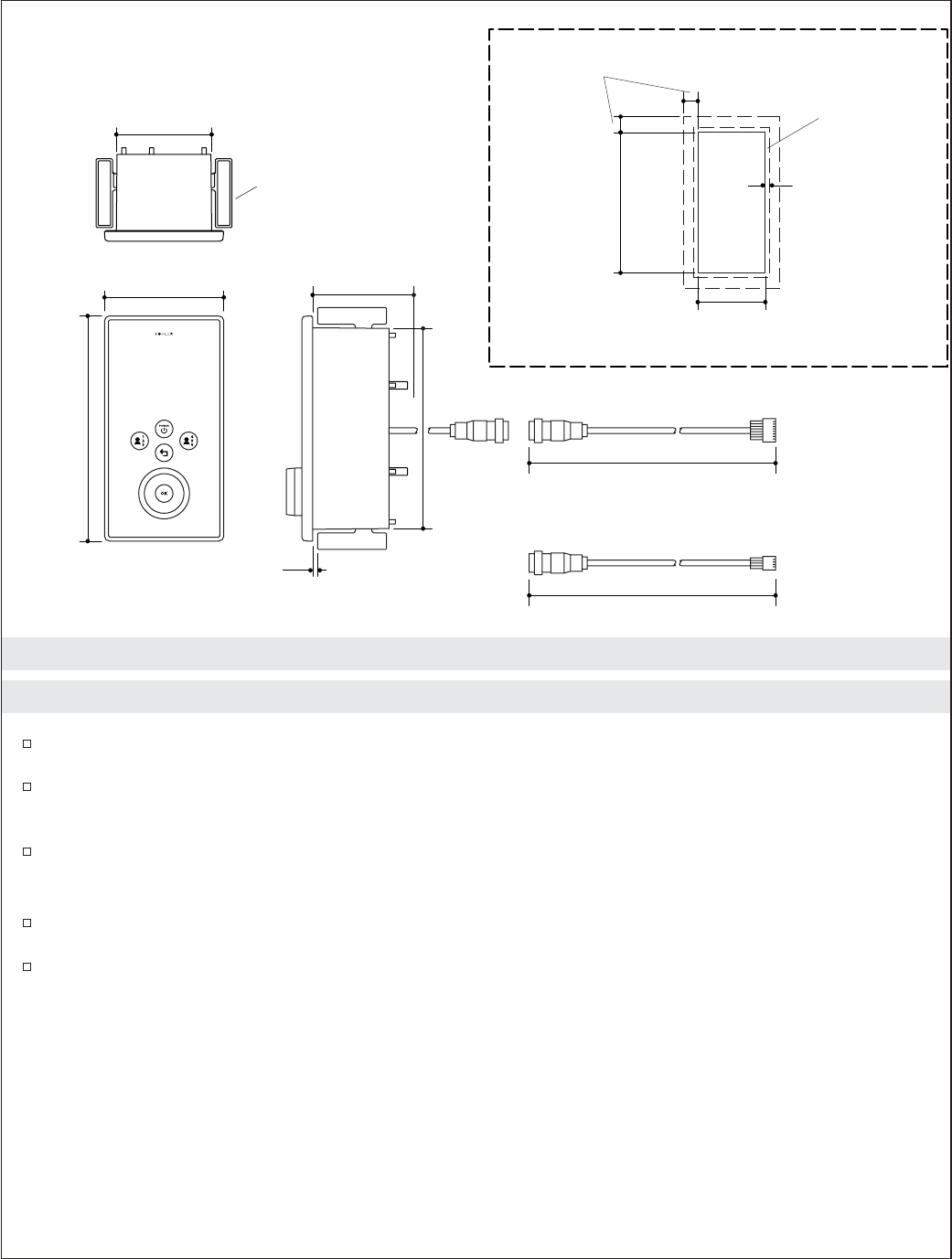
- Roughing-In 4
- Before You Begin 4
- 1. Preparation 5
- 2. Prepare the Site 6
- 3. Install the Interface 7
- 4. Complete the Installation 9
- 5. Installation Checkout 9
- 6. Troubleshooting 10
- Guide d’installation 13
- Renseignements importants 13
- Outils et matériels 14
- Raccordement 15
- Avant de commencer 15
- 1. Préparation 16
- 2. Préparer le site 17
- 3. Installer l’interface 18
- 4. Compléter l’installation 20
- 6. Dépannage 21
- Guía de instalación 24
- INSTRUCCIONES IMPORTANTES 24
- Herramientas y materiales 25
- Diagrama de instalación 26
- Antes de comenzar 26
- 1. Preparación 27
- 2. Prepare el sitio 28
- 3. Instale la interface 29
- 4. Termine la instalación 31
- 1043184-2-B 35
Related products and manuals for Tools Kohler Digital Interface K-684


 (16 pages)
(2 pages)
(28 pages)
(2 pages)
(20 pages)
(76 pages)
(68 pages)
(16 pages)
(2 pages)
(28 pages)
(2 pages)
(20 pages)
(76 pages)
(68 pages)
© 2020, manymanuals.com. All rights reserved. | 0.127 s |
 Manymanuals.com
 Manymanuals.de
 Manymanuals.fr
 Manymanuals.it
 Manymanuals.pl
 Manymanuals.cz
 Manymanuals.es
 Manymanuals-pt.com
Comments to this Manuals