4
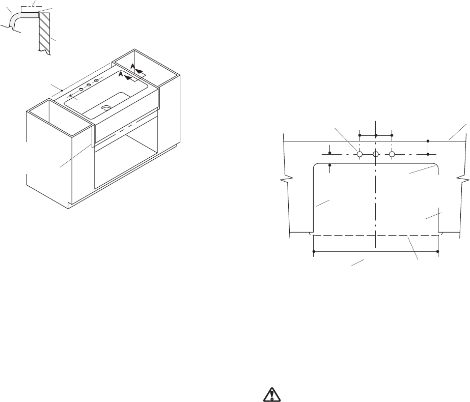
Fig. #8
Section View A-A
Sink
Sealant
Cabinet Perimeter
Countertop
“Y”
Wood
Filler Strip
(Optional)
UNDERCOUNTER SINK INSTALLATION
3.
Measure sink apron and cabinet opening to make sure
sink apron will fit into cabinet opening. If necessary,
sand opening or add wood filler strips.
4. Assemble faucet according to manufacturer’s instruc-
tions.
5. See Fig. #4. Place a thin layer of sealant (provided) at
each corner of the support where it will contact the sink.
6. Gently position sink within the frame, locating sink in
center of sink cabinet.
7. See Fig. #8. Make sure the sink rim is level and flush
with the cabinet perimeter. Adjust or shim between sink
and support if needed to obtain proper fit. Top of sink rim
must be flush with top of cabinet perimeter in order to ob-
tain proper contact with the underside of the countertop.
NOTE
: Apply additional sealant if using shims.
8. Assemble strainer or garbage disposal to sink according
to manufacturer’s instructions.
9. Using sealant between apron and cabinet is optional.
CUT-OUT POSITIONING
10.
See Fig. #9. Due to the various cut-out sizes possible,
no template is supplied. If using the K-5984 cutting
board, the minimum cut-out length is 22-3/4”.
11. Carefully measure the countertop to determine the ex-
act location of the cut-out.
12.See Fig. #8. Measure the distance from finished wall to
the center of sink faucet holes (Dim. “Y”). This dimen-
sion will be used to locate the faucet hole centerline and
back edge of the cut-out on the countertop. Make sure
the sink is positioned to provide adequate clearance be-
tween faucet and backsplash, finished wall, or support
frame. This will ensure full faucet operation when in-
stalled.
13.See Fig. #9. From back edge of countertop, locate the
dimension from finished wall to center of faucet holes
(Dim. “Y”) and draw the centerline. Add 1-1/2” to the fau-
cet hole centerline to locate the back edge of the cut-out.
Trace the cut-out opening on the countertop using a soft
lead pencil. Locate the faucet holes.
Fig. #9
Finished
Wall
1-3/8” D. Faucet Holes
Min. Cut-out If Using
K-5984 Cutting Board
Countertop
Sink
Cut-out
“Y”
1-1/2”
Min.
2” R. Max.
(Sharp Corner
Optional)
22-3/4”
4” 4”
14.Cut out the opening in the countertop, carefully follow-
ing the pencil line. Use an orbital sander or sanding
block to smooth the edge of the cut-out area and remove
all saw marks. For laminate-type countertops, all ex-
posed unlaminated surfaces near the cut-out opening
must be adequately finished and sealed to prevent dam-
age from water absorption.
CAUTION: Risk of product damage. Do not cut, drill,
or sand countertop while positioned over fixture.
15.Drill required faucet hole locations (number of holes
drilled will be determined by the fitting being used) and
install faucet to countertop according to manufacturer’s
instructions. (Sink has five faucet holes.)
16.Clean the top of the sink rim, making sure surface is
free from debris. Clean the bottom of the countertop
around the cut-out area, making sure surface is smooth
and free of defects.
17.Apply a generous bead of sealant around the sink rim
(where sink rim and countertop meet).
18.Position the countertop over the sink, being careful the
sealant provides a complete seal between sink rim and
bottom of countertop. Immediately wipe away any ex-
cess sealant with a damp cloth. Fill any voids between
rim and countertop with provided sealant.
19.Sealing gap between apron and cabinet is optional.
 Manymanuals.com
 Manymanuals.de
 Manymanuals.fr
 Manymanuals.it
 Manymanuals.pl
 Manymanuals.cz
 Manymanuals.es
 Manymanuals-pt.com
Comments to this Manuals