Kohler K-1913-R-96 Installation Guide Page 26
- Page / 136
- Table of contents
- BOOKMARKS
- Installation Guide 1
- Important Information 2
- Table of Contents 3
- Tools and Materials 3
- Before You Begin 4
- Parts Identification 5
- 1. Construct the Framing 6
- 4. Remove the Door 10
- Kohler Co. 13 1128532-2-C 13
- 6. Remove the Drip Tray 14
- 7. Disconnect the Components 15
- 8. Position the Bath 16
- 9. Level the Bath 18
- All Installations 19
- 11. Install the Drip Tray 20
- 13. Install the Door 23
- 14. Attach the Counterweights 24
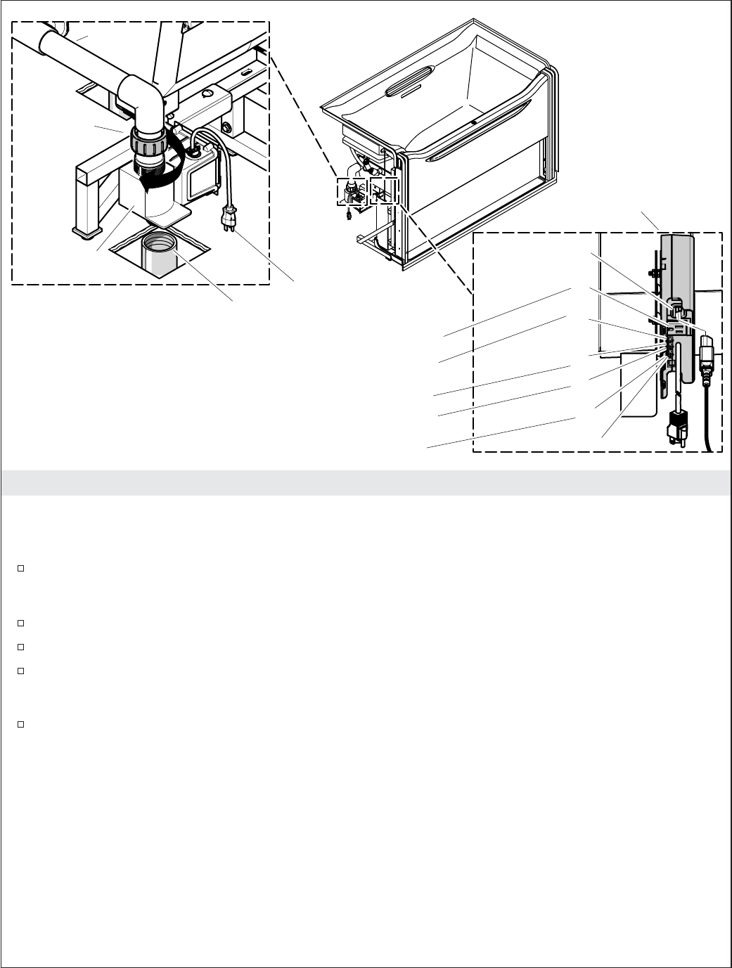
- 15. Connect the Components 26
- 16. Adjust the Bath Door 27
- 19. Install the Finished Wall 33
- Guide d’installation 43
- Informations importantes 43
- Sommaire 44
- Outils et matériels 44
- Avant de commencer 45
- Identification des pièces 46
- 1. Construire le cadrage 47
- Toutes les installations 49
- 4. Retirer la porte 51
- 7. Déconnecter les composants 56
- 9. Niveler la baignoire 60
- 13. Installer la Porte 66
- 14. Attacher les contrepoids 67
- 15. Connecter les composants 69
- 19. Installer le mur fini 76
- 20. Procédures de dépannage 76
- Guía de instalación 88
- Información importante 88
- Contenido 89
- Herramientas y materiales 89
- Antes de comenzar 90
- Identificación de las piezas 91
- 4. Retire la puerta 96
- 6. Retire la bandeja de goteo 100
- 7. Desconecte los componentes 101
- 8. Coloque la bañera 103
- 9. Nivele la bañera 105
- Todas las instalaciones 106
- 13. Instale la puerta 111
- 14. Fije los contrapesos 112
- 15. Conecte los componentes 114
- 19. Instale la pared acabada 121
- 1128532-2-C 133
© 2020, manymanuals.com. All rights reserved. | 0.330 s |
 Manymanuals.com
 Manymanuals.de
 Manymanuals.fr
 Manymanuals.it
 Manymanuals.pl
 Manymanuals.cz
 Manymanuals.es
 Manymanuals-pt.com
Comments to this Manuals