Masking Tape
8+ tubes Non-Solvent
Based Construction Adhesive
(Silicone Adhesive when installing over tile)
7-1/4" Circular Saw
and Masonry Blade
Caulk Gun
1-2 Tubes Color Matched
100% Silicone Sealant
Sanding Block
Plus:
• Standard Woodworking Tools
• Spring Loaded Braces or Lumber
(to create bracing)
• Sawhorses
• Drop Cloth
Drill & Hole Saw
(size will vary)
Breathing Protection
Shop Vacuum
Rags
High Speed Rotary Tool
with Cut-Off Wheel
Denatured Alcohol
D
E
NA
TU
R
E
D
A
LC
O
H
O
L
Jigsaw with
Grit Blade
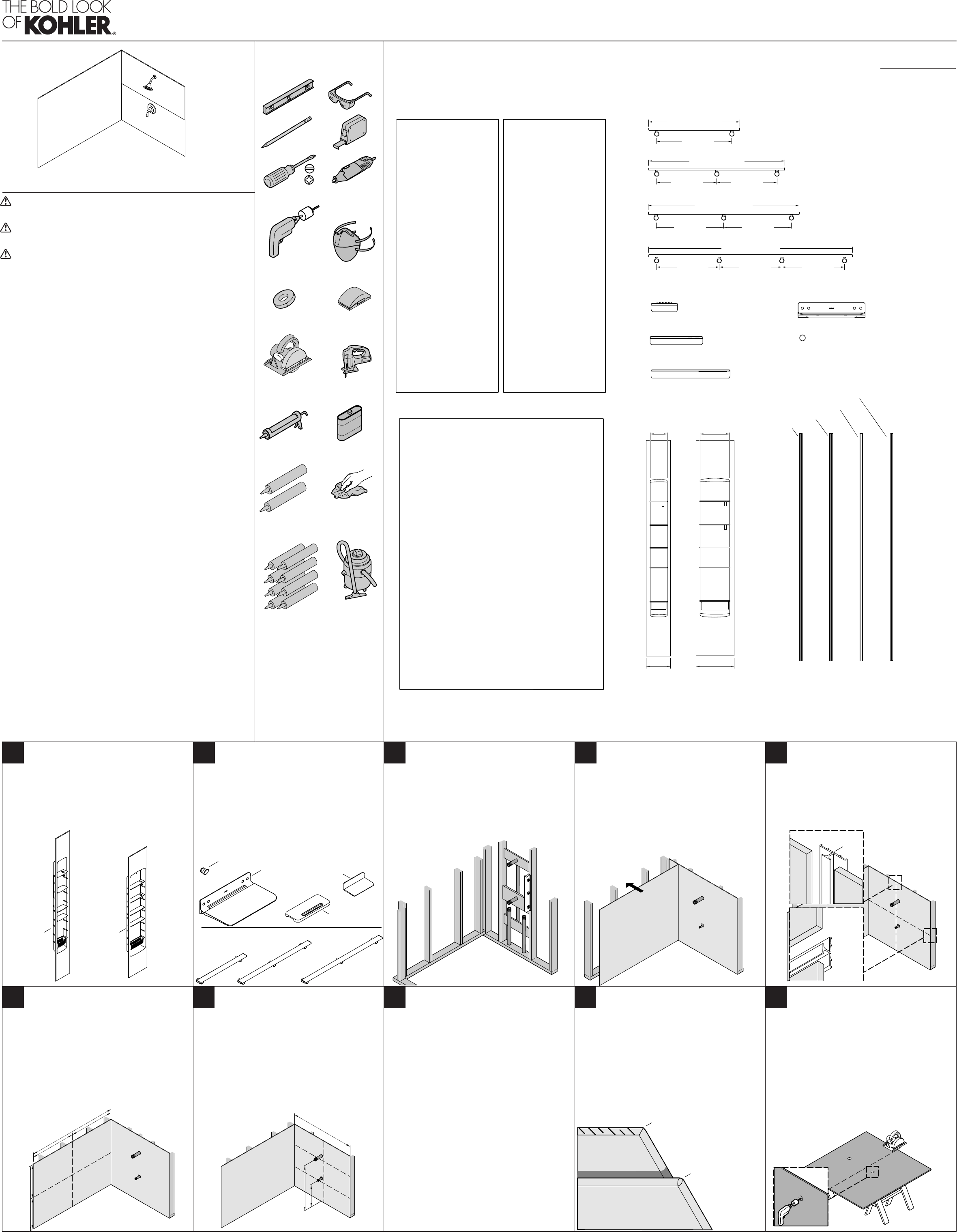
54" (1372 mm) Handrail*
40" (1016 mm) Handrail*
36" (914 mm) Handrail*
24" (610 mm) Handrail*
Right Corner Joint
Left Corner Joint
Robe Hook
7" (178 mm)
Shelf
Back Wall Layout
Right Sidewall LayoutLeft Sidewall Layout
Record your layout in the area below. Note the location of
backer material, seams, and accent walls.
21" (533 mm)
Shelf
14" (356 mm)
Shelf
Fixed Seat*
16" (406 mm)
Maximum
16" (406 mm)
Maximum
16" (406 mm)
Maximum
16" (406 mm)
Maximum
16" (406 mm)
Maximum
16" (406 mm)
Maximum
16" (406 mm)
Maximum
*** Backer board should span four studs.
* Backer board should span two studs.
** Backer board should span three studs.
2x4 backing required
24" (610 mm) long minimum*
2x4 backing required
36" (914 mm) long minimum**
2x4 backing required
40" (1016 mm) long minimum**
2x4 backing required
54" (1372 mm) long
minimum***
Attach directly to studs or 2x4 backing
17-1/2" (445 mm) minimum*
Attach directly to stud or 2x4 backing
17-1/2" (445 mm) long minimum*
2x10 backing required
33-1/2" (851 mm) minimum**
Seam Joint
Attach directly to stud or 2x4 backing
17-1/2" (445 mm) long minimum*
2x4 backing required
17-1/2" (445 mm) long minimum*
9"
(229 mm)
Locker
14-1/2"
(368 mm)
Locker
Edge Joint
Layout
Accessories
Available accessories are shown. Determine installation location prior to
wall installation. Install backer board support as indicated.
11" (279 mm) 17" (432 mm)
16" (406 mm)
Maximum
14" (356 mm)
Locker
9" (229 mm)
Locker
Back Side
Front
Side
Seam
Joint
54" (1372 mm)
(not shown)
40"
(1016 mm)
36"
(914 mm)
24"
(610 mm)
Robe Hook
Flip Down Seat
Handrails
Handrail Shelf
7" (178 mm)
14" (356 mm)
21" (533 mm)
Shelf
Uncut Edge
Cut Edge
Important: If a 9” (229 mm) or 14” (356 mm)
locker unit will be installed, follow the directions
packed with the locker unit. Do not use this
installation guide.
NOTE: The handrails, robe hook, and shelves
require 2x4 backing support.
NOTE: The flip down seat requires 2x10 backing
support.
Determine the accessories that will be installed.
Install the rough plumbing for the bath and
shower components.
Install backing support for all accessories
that require additional support following the
instructions provided with the accessory.
Record the locations of the backing on the
diagram above.
IMPORTANT: Water resistant wallboard
backing material is recommended.
Check the studs for plumb. Studs should be
within 3/8” (10 mm) of plumb.
Use shims if necessary to ensure all walls are
plumb or within 3/8” (10 mm) of plumb.
Determine if there will be vertical or horizontal
seams beyond the corner locations.
Order optional seam joints as needed.
Determine if end caps will be installed.
Order optional end caps as needed.
Back Wall Measurement:
Measure the installation area to determine the
cut dimensions for the panels.
If corner joints will be installed, subtract 1/16”
(2 mm) from the width of the back panel for each
corner joint.
If a seam joint(s) will be installed, subtact 1/16”
(2 mm) from the wall panels height or width for
each seam joint.
Mark the cut lines on the back side of the back
panel.
Sidewall Measurement:
If a corner joint(s) will be installed, subtract
5/16” (8 mm) from the width before cutting.
If a seam joint(s) will be installed, subtract 1/16”
(2 mm) from each panels height.
Record the location of the handle, showerhead,
bath spout and other components.
Mark the cut lines on the back side of the side
panels.
Optional for Installations With Ceiling Panels:
CAUTION: Risk of injury. Install the ceiling
panel prior to installing the panels. Allow the
adhesive to cure before installing the panels.
If the ceiling will be covered with the panel
material, measure and cut the ceiling panel to
size.
NOTE: Polyurethane based adhesive is
recommended for the ceiling panel.
Construct bracing or use commercial bracing to
hold the ceiling material in place while it cures.
Apply construction adhesive to the ceiling
material as shown in step 15.
With a partner, carefully lift the ceiling panel
into place.
Brace the panel tight against the ceiling
and allow it to cure following the adhesive
instructions.
IMPORTANT: For installations with a seam
joint, the cut edge of the panel MUST be
positioned opposite the seam. The vertical edge
of the seam MUST mate to an uncut, beveled
molded edge on the panel.
A seam joint may be used between the panel
and the seam, but the trimmed edge location
requirements remain unchanged.
Position the back wall panel face down on
a stand or sawhorses that have a protective
material on them.
IMPORTANT: It is recommended the panel be
cut using a power saw and an abrasive wheel or
an abrasive masonry blade.
Cut the panel to the required dimensions. Use a
jigsaw with a grit blade for contour cuts.
Repeat with the side wall panels.
From the front side of the panel, use a hole saw
to cut the holes for valving and other shower
components.
Wall Panels with Optional Joints
K-97600, K-97601, K-97603, K-97604, K-97605, K-97606, K-97607, K-97608, K-97609, K-97610, K-97611, K-97612,K-97613, K-97614, K-97615, K-97616, K-97617, K-97618, K-97619, K-97620
NOTE: Install corner joints for aesthetic look when the wall is out-of-plumb
less than 3/8” (10 mm), or the panels are cut unevenly.
The existing rough walls must be within 3/8” (10 mm) of plumb. Shim as
needed.
Use color matched silicone sealant in the joints that match the color of the
walls as closely as possible.
Cover the shower receptor with a drop cloth or other protective material to
avoid damage.
Follow the construction adhesive and silicone sealant instructions for
application and curing time.
Inspect all components for damage after unpacking, prior to installation.
A router may be used to cut the walls. The router bit will dull quickly.
If the panels are being installed over existing tile, scuff the tile using 100 grit
sandpaper to provide a better surface for adhesive contact.
11236601-2-A
1236601-2-A
Installation and Care Instructions
Record model number from box for reference.
Model Number:______________
Required Tools Rough-in Plan
2 3 4
7 86 9
5
10
WARNING: Risk of serious injury. When cutting the wall panels, take
appropriate safety measures including the use of breathing protection.
CAUTION: Risk of serious injury. Always wear safety glasses while
cutting and drilling.
CAUTION: Risk of injury. If the ceiling will be covered with the wall
material, the ceiling must be installed prior to the wall panels. Allow
sufficient time for the ceiling installation to cure before installing the wall
panels or the ceiling can fall during installation, causing injury.
CAUTION: Risk of product damage. The wall panels should be room
temperature before cutting. Allow the temperature to stabilize if the
walls were outside in a cold climate.
IMPORTANT: Dust will be generated when cutting the panels. Cutting the
wall panels should be performed outside or in a well ventilated area.
IMPORTANT! For best results, cut the walls using a masonry blade and
circular saw blade. Do not use a blade with teeth.
IMPORTANT! Leave this manual for the end user.
Read these instructions before installing or using this product.
USA/Canada: 1-800-4KOHLER
México: 001-800-456-4537
kohler.com
1


 (20 pages)
 (4 pages)


Comments to this Manuals