Kohler Generator Sets 20--2800 kW User Manual Page 21
- Page / 56
- Table of contents
- BOOKMARKS
- 20--2800 kW 1
- Installation 1
- California Proposition 6 5 2
- Table of Contents 3
- Table of Contents, continued 4
- Accidental Starting 5
- Engine Backfire/Flash 6
- Exhaust System 6
- Fuel System 6
- Hazardous Noise 7
- Hazardous Voltage/ 7
- Electrical Shock 7
- Heavy Equipment 9
- Hot Parts 9
- Moving Parts 9
- Introduction 11
- Service Assistance 11
- Section 1 General 13
- TP-5700-1 14
- Section 2 Load and Transport 15
- 2. Lifting bars 16
- 1. Lifting fixture 16
- 2.1.1 Weather Housing 17
- 2.1.2 Sound Shield 17
- 2.1.3 Subbase Fuel Tank 17
- Section 3 Location 19
- 3.3 Mounting 20
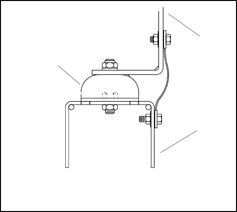
- 3.4 Vibration Isolation 21
- Section 4 Air Requirements 23
- 4.2 Air-Cooled Generators 24
- 4.3 Forced Air 25
- 4.4 Air-Vac Cooling System 26
- 4.5 Air Vent 27
- 4.6 Liquid-Cooled Models 28
- 4.8 Remote Radiator Cooling 29
- 4.9 City Water Cooling 30
- 4.10 Cooling Tower 30
- 4.11 Block Heaters 32
- 4.12 Recommended Coolant 32
- Section 5 Exhaust System 33
- 5.1 Flexible Section 34
- 5.2 Condensation Trap 34
- 5.3 Piping 34
- 5.4 Double-Sleeve Thimbles 35
- Section 6 Fuel Systems 37
- 6.2 Main Fuel Tank 38
- 6.3 Fuel Lines 38
- 6.4 Transfer Tanks 39
- 6.5 Auxiliary Fuel Pumps 40
- 6.6 Gasoline Fuel Systems 41
- 6.7 Natural or LP Gas Fuel 42
- TP-5700-6 43
- 6.8 Flexible Connector 44
- 6.9 Gas Piping 44
- 6.10 Fuel Regulators 44
- 6.12 Vapor Withdrawal Systems 45
- 6.14 Dual Systems 45
- (Natural and LP Gas) 45
- 6.15 Natural Gas 46
- 6.16 Combination Gas-Gasoline 46
- 7.1 Batteries 47
- 7.2 Electrical Connections 48
- 7.3 Load Lead Connections 48
- 7.4 Terminal Connector Torque 49
- Remote Annunciator 50
- 14-Relay Dry Contact Box 50
- Front View Side View 50
- GENERATOR JUNCTION BOX 52
- Appendix A Abbreviations 53
- TP-5700 7/93d 56
Related products and manuals for Generators Kohler Generator Sets 20--2800 kW
 (52 pages)
© 2020, manymanuals.com. All rights reserved. | 2.265 s |
 Manymanuals.com
 Manymanuals.de
 Manymanuals.fr
 Manymanuals.it
 Manymanuals.pl
 Manymanuals.cz
 Manymanuals.es
 Manymanuals-pt.com
Comments to this Manuals